
Breakwaters are widely used structures to control coastal erosion and to ensure safe access to harbors. They are barriers that are frequently displaced perpendicularly to the dominant wave direction, which absorb, refract, diffract and reflect part of the wave energy, therefore reducing the amount of energy that reaches the shoreline. Wave height is thus reduced therefore facilitating the harbourage of ships and controlling erosion. Breakwaters are also used to control cross-shore sediment transport inside harbor basins, which is in turn useful to reduce the need for dredging. Removing sediments from harbor basins is problematic for the need to displace them. Harbor muds, infact, may be contaminated and need proper treatment before disposal. Different types of breakwaters can be used, which can be built by using several different materials. They also differ for their permeability, the possibility to be overtopped and therefore the resulting reduction of the energy of waves. Breakwaters have a significant impact on the wave regime and therefore coastal dynamics and morphodynamics. They may also imply unintended consequences. The dissipation of energy and relative calm water created in the lee of the breakwaters often encourage deposition of sediment. This can lead to the formation of a tombolo, which traps longshore sediment drift and may cause adverse effects, leading to beach sediment starvation and increased erosion downdrift. This may then lead to further engineering protection being needed downdrift of the breakwater development (Figure 1).
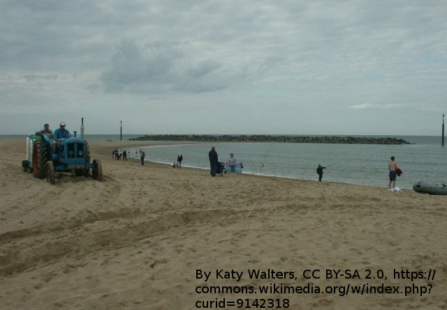
Figure 1. Tombolo in the leeward side of a breakwater. By Katy Walters, CC BY-SA 2.0, https://commons.wikimedia.org/w/index.php?curid=9142318.
Breakwater design should be first driven by the identification of the optimal configuration of the shoreline. In fact, breakwaters are built to change the coast in some way. Then, understanding the likely incident wave and water level conditions, how the breakwater influences the incident wave energy distribution and tidal flows on the beach, and the beach’s response to the new conditions are the three key elements for selecting an appropriate geometrical layout of a nearshore detached breakwater scheme.
The most frequent purpose of a breakwater is to provide protection against waves. The protection may be provided for a beach or a harbor. A breakwater may also serve to reduce the amount of dredging in front of a harbor entrance. At locations where little or no natural protection exists, breakwaters often serve as quay facilities as well. A fourth possible important purpose of a breakwater can be to guide the currents in the channel or along the coast. Breakwaters may serve to satisfy one or more of the above requirements.
Design of breakwaters need to be supported by adequate information. Bathymetry is extremely important. For instance, one should consider that the volume of material that is needed to build a rubble mound breakwater increases quadratically with water depth. Information on wave and tidal regime is the main input to breakwater design. Meteorological information is also important. Winds are not only important for local wave generation, but can also be important for estimating the quantity of overtopping by spray from the broken waves. Temperature data can be important for the selection of construction materials. Special concrete must be used if repeated cycles of freezing and thawing are expected. Knowledge of the local soil conditions is also needed to design the foundation of breakwaters. It may also be helpful to collect information on historical changes in beach morphology. Finally, the availability of construction material is another important driver.
Massie (1976) (available here) provides an extensive review of breakwater types. They include:
- Air bubble curtains: submerged pipelines releasing air to induce currents which tends to break waves.
- Artificial beaches: formed by gravel or sand that cause wave breaking.
- Rubble mound front: permanent structure constituted by a vertical monolithic structure protected by a rubble mound.
- Composite - Vertical monolithic top: permanent structure consisting of a rubble mound base surmounted by a monolithic vertical structure.
- Floating flexible: temporary flexible bouyant floating device which absorbs wave energy.
- Floating rigid: a large floating body, like a ship or a pontoon.
- Monolithic floating: a caisson or ship that is partially floating therefore allowing its placement over mud materials.
- Monolithic with porous front: a permanent monolithic structure having a porous front wall.
- Monolithic with sloping front: a monolithic structure with the upper portion of the vertical face sloping back at an angle of in the order of 45 degrees.
- Monolithic vertical: permanent structure consisting of large elements stacked upon each other in a regular pattern forming a massive vertical wall.
- Pile row: permanent structure formed by driving a row of piles either close together or spaced apart.
- Resonant breakwater: a series of rectangular basins connected to a harbor entrance such that each is tuned to absorb energy of a given wave period.
- Rubble Mound with armor units: a permanent structure consisting of layers of stone and gravel protected on the exposed surfaces by a layer of randomly placed or positioned artificial armor units. A massive structure may be incorporated in the crest to save material.
- Rubble Mound - Stone: permanent structure consisting of successive layers of stone. The exposed surface is covered with heavy armor stones.
- Submerged - vertical or rubble mound: permanent structure sometimes used to create an artificial tombolo.
The following consideration may be useful to select the optimal type of breakwater:
- Rubble mound structures are the most durable, and as such are best suited to extremely heavy wave attack.
- Monolithic structures use less space and material; this is especially true in deep water.
- Special types of breakwaters are usually best suited to specific special applications.
Rubble mound and vertical walls are the most frequently used types of breakwaters.
Rubble mound breakwater is the most common breakwater used for shore protection. It consists of several armor layers with different densities. A mound is an artificial embankment or ridge composed of heavy units of assigned size. They may be built by dumping material from the sea bottom or bringing material from other locations. Rubble is irregularly shaped, rough units, ranging in size up to 30 m3 each and up to nearly 90 tons each in weight. The units are usually not prepared other than removing very sharp angles and any objectionable protruding points. Hard rock, which is more desirable, usually consists of either granite or traprock (fine-grained igneous rock). Limestone, dolomite, and sandstone are undesirable because of their lesser hardness, toughness, and durability. In older structures the units consist of large cubical or rectilinear blocks of quarried stone. Since the rubble must be available in large sizes, the quality, condition, and shape of stone are important. Each piece should be devoid of planes of weakness, have a specific weight not less than 2.6 tons per cubic meter, and have excellent resistance to abrasion and weathering. Since 1950, a number of concrete armor units have been developed; the prevalent types are tetrapods, tribars (see Figure 2), and dolosse. Smaller concrete armor units can often be substituted for larger quarry stones and still obtain comparable protection of the mound of rubble. No reinforcing steel or steel lifting eyes are used in dolosse and tetrapods; consequently, corrosion is not a problem, and unit cost is minimized. Dolos and tetrapod units are less vulnerable to damage during placement and storms than the various other types of concrete armor units. 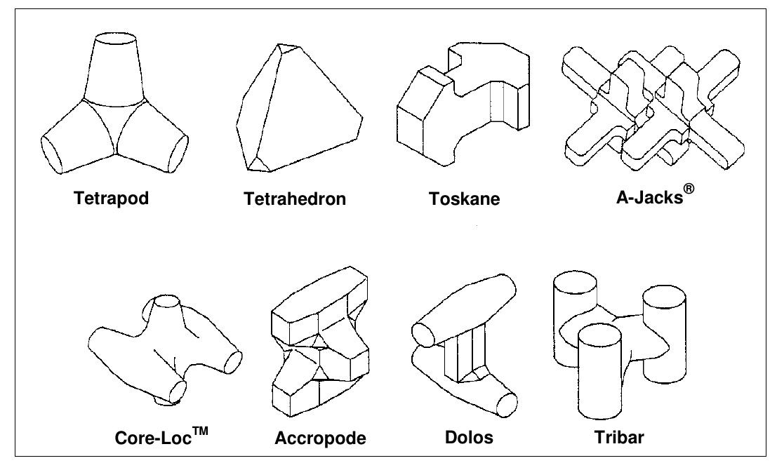
Figure 2. Concrete harmour units. From Lagasse et al. (2009).
Breakwaters can be subdivided into two main categories, by distinguishing between structures that are designed to allow, or not, overtopping by waves. The use to be made of the area directly leeward of a rubble mound breakwater plays an important role in the choice between an overtopping or non-overtopping rubble mound structure. In general , the less important or critical the activity on the lee side, the more overtopping that may be allowed. Overtopping may damage the crest of the breakwater and therefore appropriate protections should be designed.
Rubble mound breakwaters are often constructed in layers, to ensure the integration of the strengths of different materials. For instance, layers made by fine sediments may be used to reduce the permeability of the structure, but then they should be protected by wave action with a cover layer made by large size units. Figure 3 and Figure 4 show schemes of typical structures for overtopped and non-overtopped breakwaters, respectively. 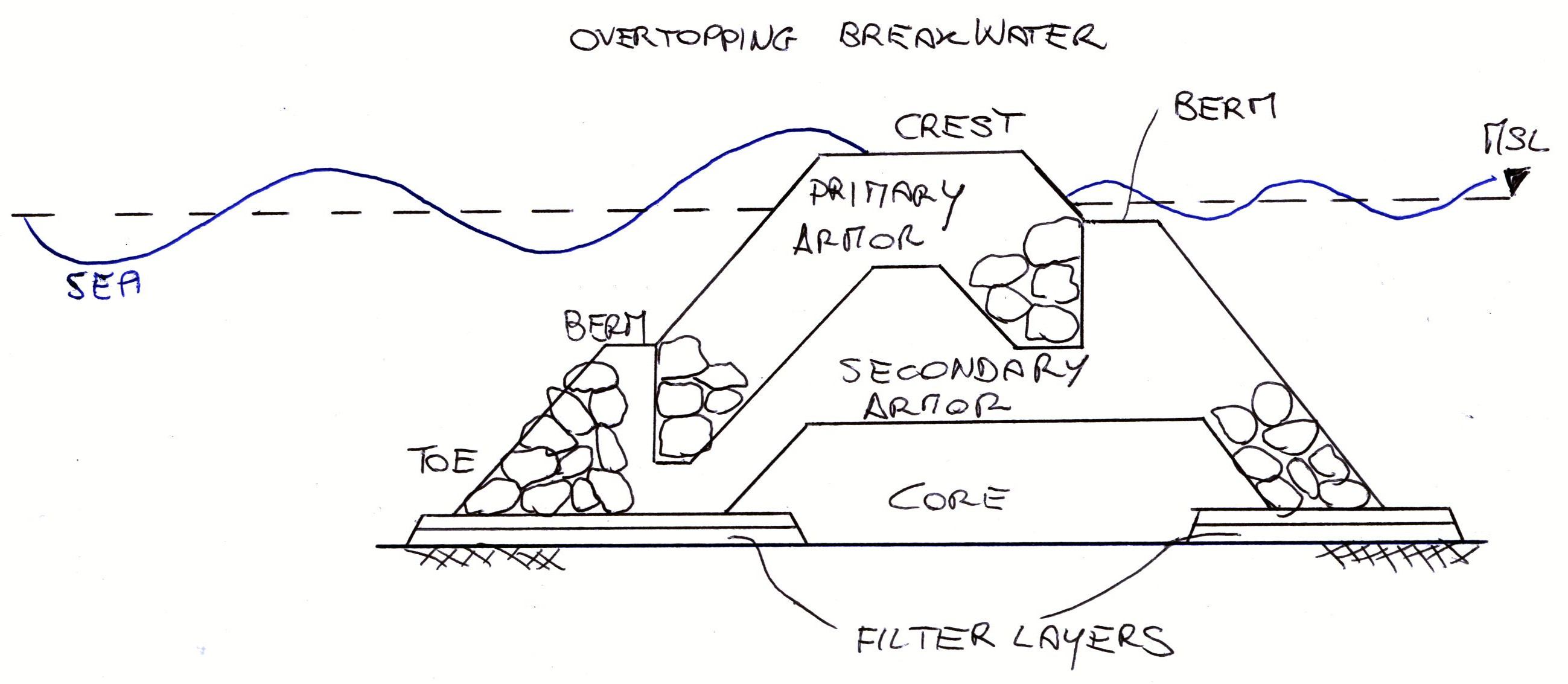
Figure 3. Typical structure of a overtopped breakwater.
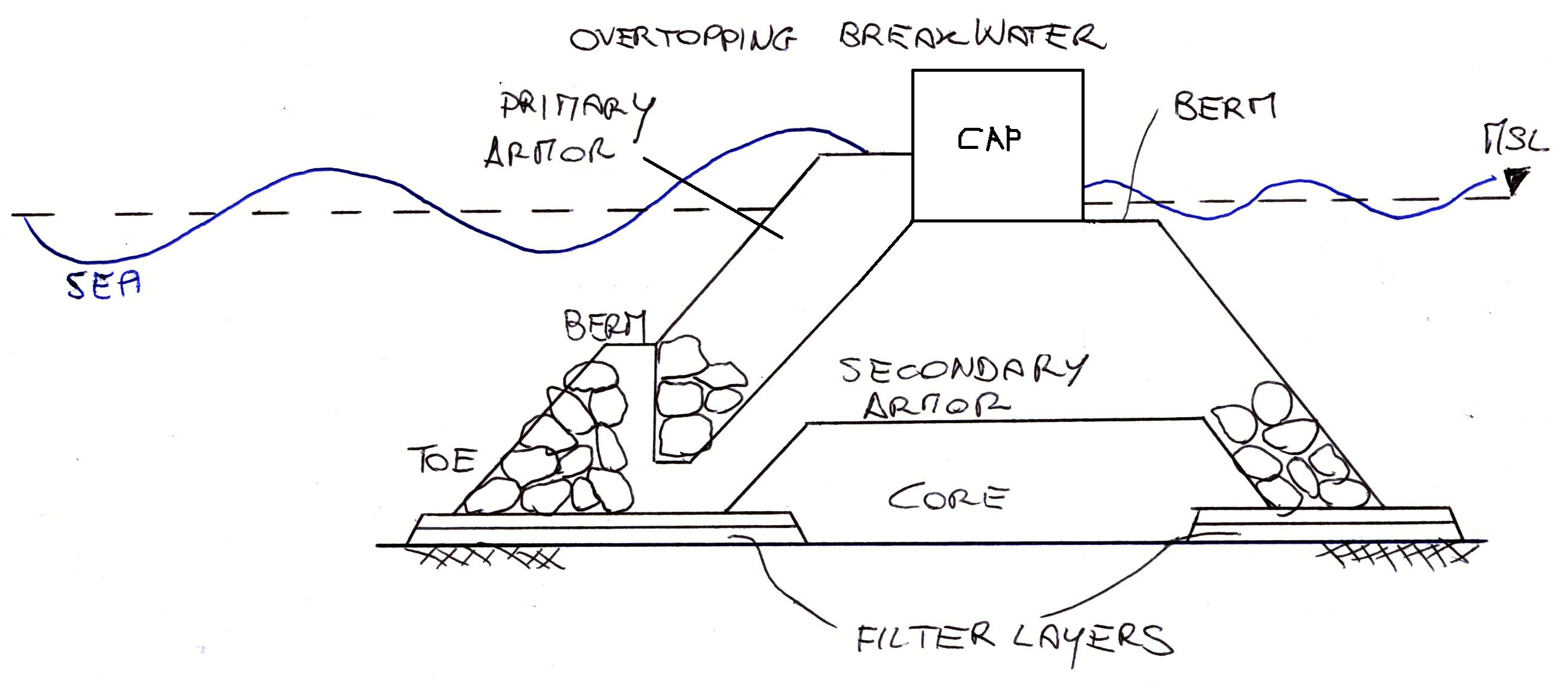
Figure 4. Typical structure of a non-overtopped breakwater.
A relevant issue and design decision is related to the permeability of the core of the structure, which regulates the permeability of the whole breakwater. A low core permeability can lead to large pressures in the armour layer therefore reducing its stability. The permeability of the core depends on the materials used and the distance at the water line between the armour layer and the impermeable layer.
As a general rule, each layer of the breakwater must be designed to avoid that finer material from an underlying layer is washed through the voids of the upper layer. Obviously, the outer layers must be designed to withstand the expected wave attack. The choice of construction materials is largely determined by its availability. Other constraints maybe dictated by the strength of the sea bottom. If sand is present, a filter must usually be constructed. Once a breakwater has been conceived, its cost must be carefully evaluated in order to identify a sustainable solution.
Wave run-up is defined as “the landward extent of wave uprush measured vertically from the still water level” (Melby, 2012). Water level fluctuation can considerably exceed the amplitude of the incident waves. For example, when waves are fully reflected by an impermeable vertical barrier, the water level fluctuation at the wall is theoretically two times the height of the incident waves. Run-up is caused by the breaking of the waves which implies that a portion of their momentum is transferred to a tongue of water rushing up the slope where breaking occurs. We indicate the run-up with the symbol R and define it as the maximum vertical elevation reached by the aforementioned tongue with respect to still water level (Figure 5). It is implied in this definition that the crest of the slope is higher than the run-up.
When regular waves are considered, a unique relationship exists between R, wave properties (height and period), and structure characteristics (toe depth, slope angle, roughness, porosity, and foreshore slope). Therefore, R may be given by a relationship that can be written in the form
R = f(Hi, T, ht, α, β, r, n)
where (Figure 5):
- Hi is the incident wave heigth;
- ht is the depth at the toe of the slope;
- n is the porosity of the slope;
- r is the roughness of the slope;
- T is the wave period;
- α is the slope of the structure;
- β is the slope of the foreshore.
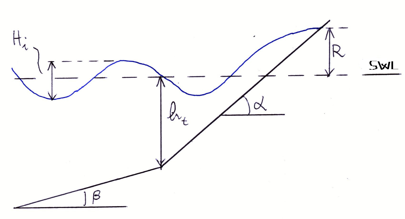
Figure 5. Dynamics of wave run-up.
The energy of the waves is partially dissipated by breaking, partially reflected, and partially expended in run-up. Wave behaviors along with the behaviours of the breakwater determine the amount of the momentum that is expended in run-up. For steep slopes the reflection is greater and the run-up is, in general, less. On the other hand, for very flat slopes, energy is dissipated by friction during the run-up, which is then less than the maximum. Nearly all of the run-up information available is of an experimental nature, and most applies to impervious structures such as dikes. A more complicated situation occurs with irregular waves.
Several empirical formulations have been proposed to estimate the vertical wave run-up height above the still water level, which is often defined in terms of the run-up level which is exceeded by only 2% of the incident waves, that is usually denoted with the symbol R2%. Van Gent (2001) has presented data from laboratory experiments for steep slope structures. The test program consisted of tests with single and double-peaked wave energy spectra, represented by a train of waves. The water level was varied to have different water depth values at the toe of the dike. The results were well interpolated by the relationship
R2%/Hi = 2.3 γsfγbermγδζ0.3, for 1<ζ<30
where:
- ζ = tan(α)/s0.5 is the surf similarity parameter;
- α = slope of sea bottom;
- s = Hi/L0 is the wave steepness;
- L0 is wave length in deep water;
- Hi is significant wave height at the toe of the structure;
- γsf is safety factor (usually taken as 1.2);
- γberm is berm factor, if a berm is present on the offshore side of the breakwater;
- γδ is oblique wave factor, where δ is the attack angle of waves with respect to the perpendicular to the breakwater.
Empirical relationships are also provided for the berm factor, which depends on Hi and the size of the berm, and the oblique wave factor, which depends on the attack angle of waves.
If the crest of the breakwater is placed at a lower elevation with respect to the maximum run-up, then up-rushing water will spill on to and above the crest of the structure. Overtopping is usually measured in terms of volume of bypassing water per unit time and crest length. When the overtopping flow is considerable water must return to the sea through apertures or through the breakwater itself, therefore originating currents. When overtopping occurs, waves can be generated on the lee side. To evaluate their height, let us denote with Ht and Zc the wave height on the lee side and the elevation of the crest of the breakwater on still water level, respectively. Furthermore, let us denote with Kt the wave transmission coefficient, that is defined as the ratio of the transmitted wave height Ht at the leeside to the incident wave height Hi at the breakwater seaward, namely:
Kt = Ht/Hi.
Then, the following rules of thumb are suggested (Massie, 1976):
for Zc/Hi > 3/4, minor waves are generated on the lee side; for Zc/Hi =0, Kt ~ 1/2; for Zc/Hi < -1/2, Kt > 3/4.
The above equations can be used with regular as well as with irregular waves if the significant wave height is taken to characterize the spectrum. The rules only provide a qualitative indication.
Several researchers attempted to provide relationships to estimate Kt. A first empirical formula was proposed by Van der Meer (1990), who proposed a linear relationship between Kt and the submergence divided by the incident wave height. Van der Meer formula reads as:
Kt = -0.30 Rc/Hi + 0.46
where Rc is the crest freeboard, namely, the elevation of the crest of the breakwater above mean sea level. The above relationship is valid for 0.1≤Kt≤0.8 and is conditioned by the assumption that the relative crest height is the main driver of the transmission. Other relevant variables like permeability of the structure are neglected.
Van der Meer and Daemen (1994; available here) introduced a second relationship which takes into account a large number of drivers, which is given by
Kt = a Rc/D50+b
where D50 is the sieve diameter corresponding to 50% of the weight of the core material. It is been shown that a depends on the relative wave height Hi/D50. b is the transmission coefficient for not emerging structures (Rc = 0) which depends again on relative wave height, the width of the berm and wave period (see Van der Meer and Daemen (1994)). The limits of validity of the above relationship are:
- -1 ≤ Hi/D50 ≤6;
- -0.07 ≤ Kt≤0.75
and another constraint in terms of wave steepness that is not discussed here (see Van der Meer and Daemen (1994) for more details).
The above relationships neglect the effect of permeability and refer to crest height placed above the mean sea level. Recent literature presented the results of laboratory and field experiments that provide more refined guidance to estimate the effect of wave transmission. Yuliastuti and Hashim (2011), which is available here, provide a recent overview of several empirical relationship that refer to submerged breakwater (with the crest elevation placed below the mean sea level).
Besides the impact of breakwaters on wave height, the effect of refraction and diffraction should be evaluated, which causes a change of wave direction.
Breakwaters create a barrier between two water fronts, where the sea side is characterised by higher kinetic energy with respect to lee side. The difference in energy causes the transfer of water volumes towards the lee side, by permeability, overtopping, or flow through the apertures. For continuity, a return flow must establish, either through the apertures or through the structure. To activate the return flow, a higher water elevation is needed on the lee side, to compensate with potential energy the excess of kinetic energy on the sea side. Water set up may have an impact on beach morfodynamics and therefore needs to be evaluated.
Recent analyses highlighted that the set up originated by partially submerged or submerged breakwaters may originate current in the along shore direction, which may trigger unexpected beach erosion. Water set up is not yet fully understood.
For a submerged breakwater, by neglecting wave breaking, a physical model for the set-up was proposed by Longuet-Higgins (1967), by equating the flux of momentum on the sea and lee sides. The proposed relationship is given by

where Ht is wave height on the lee side, HT is the sum of incident and reflected wave height, k1 and k2 are wave numbers on the sea and lee side, respectively, and d1 and d2 are sea bottom depths with respect to mean sea level on the sea and lee side, respectively.
Assessment of stability of armour units is a key step in breakwater design. The procedure are all in all similar to those that are usually applied for groins. The subject has been extensively treated in this page to which the interested reader may refer.
Designing breakwater involves the assessment of several different issues ranging from stability of the structure, its submergence, permeability, transmission, water set up and others. The above notes provide a first introduction to the topic. Practical guidelines for design are provided here.
Lagasse, P. F., Clopper, P. E., Pagán-Ortiz, J. E., Zevenbergen, L. W., Arneson, L. A., Schall, J. D., & Girard, L. G. (2009). Bridge scour and stream instability countermeasures: experience, selection, and design guidance: Volume 1 (No. FHWA-NHI-09-111). National Highway Institute (US).
Longuet-Higgins, M.S., On the wave-induced difference in mean sea water level between the two sides of a submerged breakwater - Journal of Marine research, 25:148–153, 2 1967.
Massie, W. W. (1976). Coastal engineering. Volume III: Breakwater design.
Melby JA (2012) Wave Runup Prediction for Flood Hazard Assessment. ERDC/CHL TR-12-24 Technical Report.
Vicksburg MS: Coastal and Hydraulics Laboratory, U.S. Army Engineer Research and Development Center. 126 pp.
Yuliastuti, D. I., & Hashim, A. M. (2011, February). Wave transmission on submerged rubble mound breakwater using L-blocks. In Proceedings of the 2nd International Conference on Environmental Science and Technology (Vol. 6).
van der Meer, J. W. (1990). Data on wave transmission due to overtopping. Delft Hydraulics.
van der Meer, J. W., & Daemen, I. F. (1994). Stability and wave transmission at low-crested rubble-mound structures. Journal of Waterway, Port, Coastal, and Ocean Engineering, 120(1), 1-19.
Last modified on April 21, 2020
- 1131 views